Comrades! Let me introduce Chernobyl Simulator, a port of the game Chernobyl: The Legacy Continues, that was released in 1998 for Windows 3.1 and Windows 95. Its original developers gave me the permission to distribute an installer for modern 64-bit Windows, that you can download for free on the project repository page.
In this educational game, you have to keep Chernobyl reactor number 3 running, fixing any malfunctions that arise, while maintaining the whole operation on a tight budget (any resemblance to actual events is purely fortuitous). The game serves as a pretext to learn about RBMK reactors and nuclear power plants in general.
The model is simplified but realistic enough to have a 100 page manual. Because it is more a general reference than a tutorial, and the software has some quirks, this article serves as a guide for your very first steps in the game. It completes the manual by explaining in greater detail how to refuel the reactor, how to manage the plant while it is off-line, and gives some ideas for further experimentation.
- 1 Introduction
-
2
Rxmodel
- 2.1 Timer and Alarms
- 2.2 Main menu
- 2.3 Control panels
- 3 Reactor refueling
-
4
Off-line operations
- 4.1 Core cooling
- 4.2 Condensate system
- 4.3 Feedwater system
- 5 Malfunctions
- 6 Next steps
1 Introduction
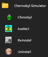
The installer creates the following start menu shortcuts:
- Chrnobyl: introduction video that leads to Icselect.
- Icselect: interface to choose between four difficulty levels for Rxmodel.
- Rxmodel: the actual simulator.
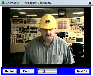
Chrnobyl is the program that displays the introduction video. While playing, the simulator shows similar videos, either as a sermon when something goes wrong, or as an hint to fix malfunctions. The sermons will teach you how (not) to operate Chernobyl under pressure from your supervisor.
Icselect is the level selection window.
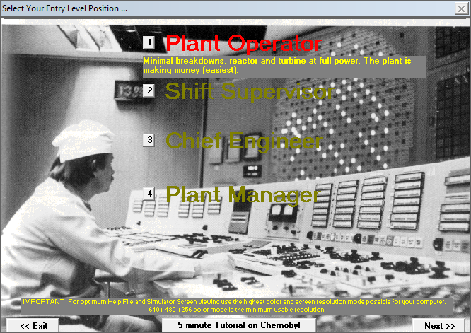
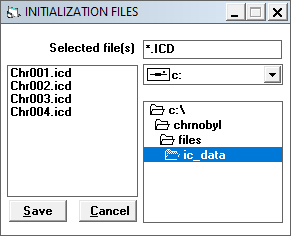
The four roles correspond to initial condition files (IC files) in
C:\CHRNOBYL\FILES\IC_DATA. They define the initial state of the simulation,
with a lower initial power level corresponding to an increased difficulty.
(There is also C:\CHRNOBYL\FILES\SAVED that looks like the default save
directory. For some reason, it already contains the IC files from IC_DATA,
plus two extra ones.)
The button 5 minute tutorial on Chernobyl opens the in-game help system with an introduction to the simulator interface.
There are other slide decks included with the game, accessible under the Help menu in Rxmodel. You can also find most of this information in the manual. This is the key resource to learn about the context of the game.
2 Rxmodel
Rxmodel is the simulator. The game interface is a little bit convoluted. Not only are there a lot of controls, but they are split into multiple windows that you have to navigate between. Fortunately, modern high-resolution screens make this task easier than it was back then. Before continuing, you should complete the 5 minute tutorial on Chernobyl.
2.1 Timer and Alarms
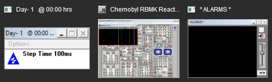
Running Rxmodel opens the main simulator window that contains the power plant controls, with two additional minimized windows:
- Timer
- Alarms
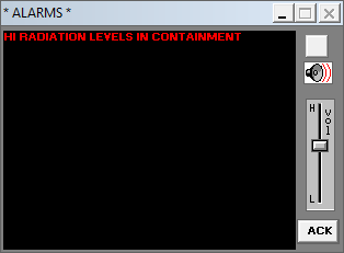
Alarms are the main way to know when something is not operating properly.
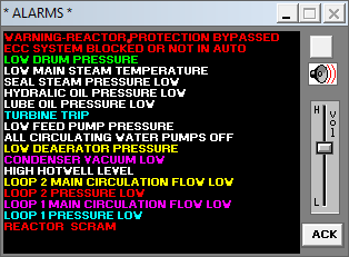
While unmuted, new messages ring the alarm until you click on the acknowledge button. Note that by the time a message appears, it may already be too late…
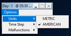
You will probably not need the Timer window, but for completeness, here are its settings:
- Units: you should select American units to follow the manual indications, although the Soviet Union relied on the metric system.
- Time step: increase performance on slow systems (shouldn’t be necessary unless you play on a potato).
- Malfunctions: toggle random events that cause issues to some parts of the plant. You can find the same item in the main menu under Extras.
2.2 Main menu
The main menu contains the following items:
- File: Save and Restore IC files.
- Displays: overview of the plant operation. Most of the game is about closely monitoring the trend charts and alarms to quickly respond to malfunctions.
- Schematics: help you track the source of an issue or monitor a system during an operation.
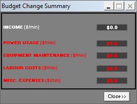
- Budget: losses and profits. When you are over budget, you can no longer buy new fuel bundles or repair malfunctioning equipment.
- Window: automatically arrange the nested windows.
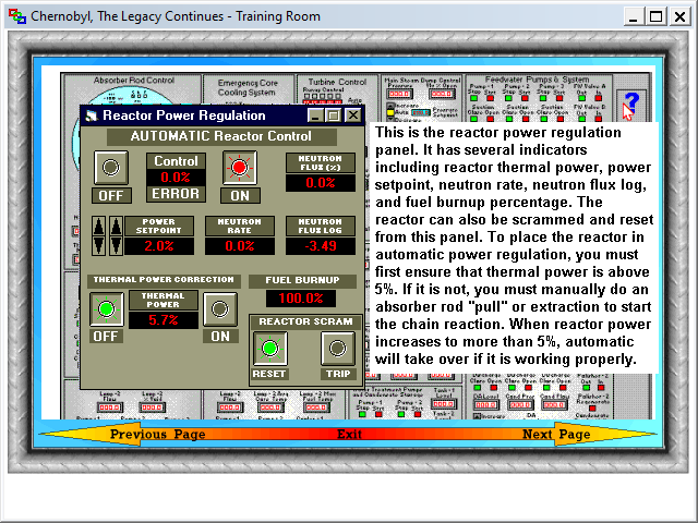
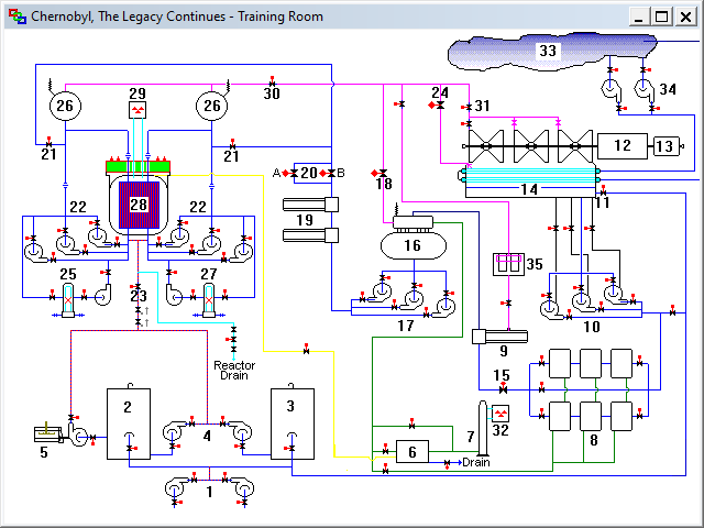
- Help: the training room, that contains the game documentation.
While you can find most of the training room information in the manual, one section is noticeably easier to navigate. The Overview of the Chernobyl Plant Systems provides an interactive schematic diagram that links each system to its detailed description. This is equivalent to the section “System by System Description of the Chernobyl Plant Cycle” from the manual, except you have to seek each description yourself.
As part of this port, I added a new Extras menu that wasn’t in the original game. It contains the following items:
- Pause: pauses the simulation.
- Malfunctions: toggles malfunctions, same as in Timer.
- Fuel: toggles fuel burn-up, so you don’t have to refuel.
- Videos: toggles in-game videos.
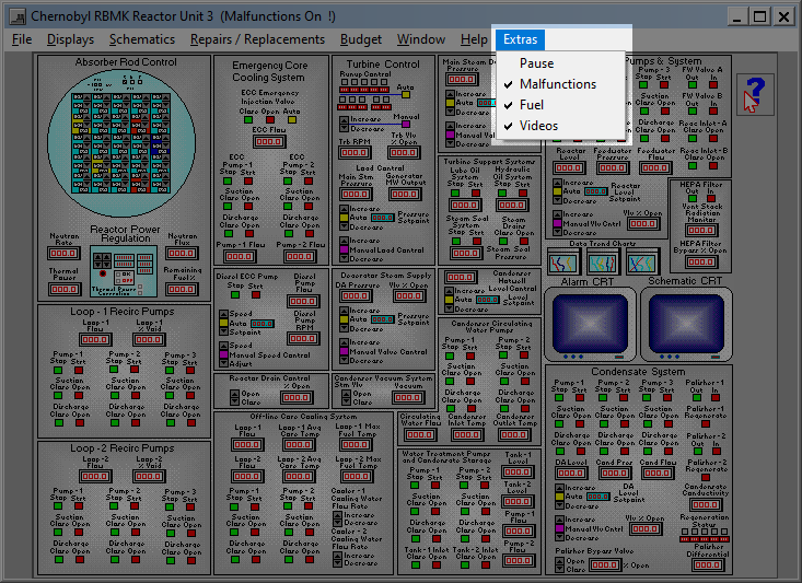
Until you are comfortable with the main systems, you should turn malfunctions off. If you don’t, you will receive alarms about random failures in some part of the plant you may not know about yet.
2.3 Control panels
The central area contains the power plant control panels:
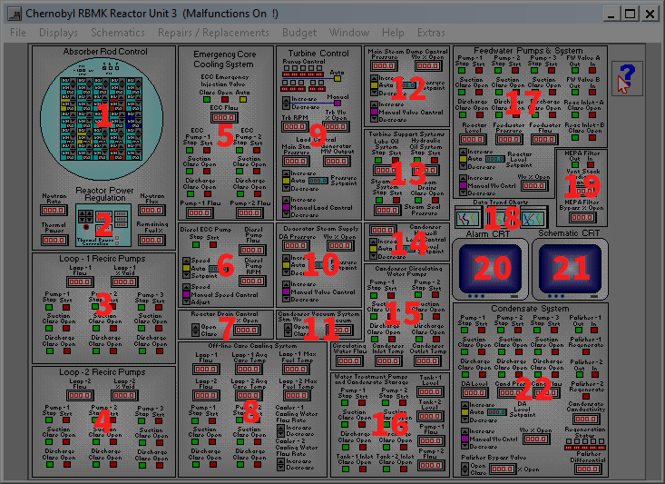
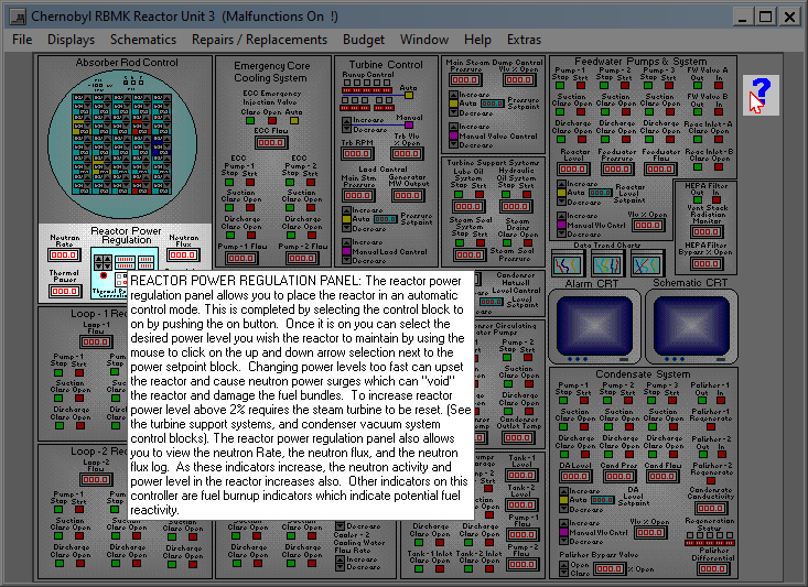
You can slide the help cursor from the top-right to quickly get information on a panel:
Left-clicking on a panel opens the associated controls in a nested window.
3 Reactor refueling
Early in the game, you will have to replace burned-up fuel bundles in the reactor core. Before continuing, you should read the section “Reactor refueling” from the manual.
Let’s start by loading the first level:
- Select the first entry in Icselect (or restore
C:\CHRNOBYL\IC_DATA\IC_0001.ICDfrom Rxmodel). - Disable Extras > Malfunctions.
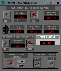
- Open the Reactor Power Regulation panel.
The Fuel Burn-up display indicates the total percentage of reactivity left in the fuel. Below a certain threshold, that depends on multiple factors, the reactor can lose criticality: the nuclear chain reaction becomes unsustained.
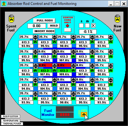
To control the reactivity, the core is traversed by rods that absorb neutrons, thereby reducing the neutron flux. Open Absorber Rod Control to see the fuel channel matrix with the control rods.
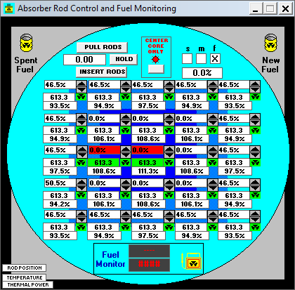
Each channel has the following information:
- Absorber rod position (inserted percentage, 0% means fully pulled back).
- Fuel temperature (the two hottest channels are highlighted in red).
- Thermal power output (percent of operating maximum).
Because the reactor flux depends on parameters such as Xenon poisoning, it is easier to evaluate the remaining reactivity by observing the control rod positions. When all of them reach 0%, you are guaranteed to lose criticality, as the absorber rods cannot be pulled back further.
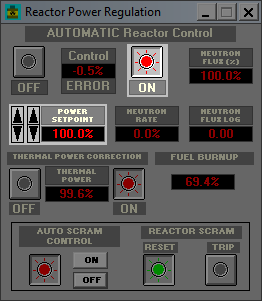
When Automatic Reactor Control is On in the Reactor Power Regulation panel, the rod positions are adjusted automatically to maintain the Power Setpoint.
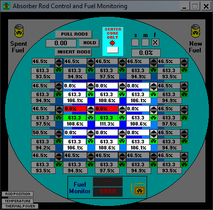
If Center Core Only is set in the Absorber Rod Control panel, the automatic reactor control system adjusts the outer rods only, leaving the center ones to the operator. In the following figure, the manually controlled rods at the center are fully pulled back, which leaves a greater control range to the automatic regulation system.
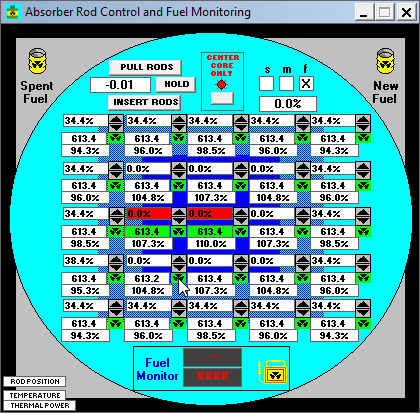
Chernobyl supports online refueling to replace used fuel assemblies while the plant is operating. To determine the order in which to replace them, you can examine each fuel channel for the potential reactivity left:
- Left-click and hold the Fuel Monitor located at the bottom.
- Move it over a fuel channel.
- Align the ionizing radiation symbols.
- Wait until the channel turns blue, indicating it has been selected.
The two displays next to the fuel monitor show the remaining reactivity and the number of fuel rods in the selected channel. You should try to refuel channels that have the lowest remaining reactivity first. Replacing fuel assemblies too soon wastes their remaining potential reactivity, increases spent fuel storage costs, in addition to the cost of a new bundle.
The game doesn’t always register the click release event, which keeps a channel selected and blocks further refueling operations. Try to take the fuel monitor again and release it over another channel until the fuel monitor displays turn off.
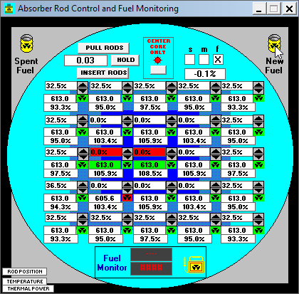
Once you’ve identified a depleted channel, you can begin removing its fuel bundles:
- Move the cursor over the channel ionizing radiation symbol.
- Left-click and hold to take one fuel bundle out.
- Move the bundle over the Spent Fuel bucket at the top-left.
- Align the ionizing radiation symbols.
- Release to dispose of the fuel bundle.
Each channel has two fuel bundles, each containing 5 fuel rods. A blue ionizing radiation symbol denotes a half-empty channel, so you have to repeat the procedure to remove all the fuel assemblies. When the symbol turns red, the channel is empty.
To load an empty channel with new fuel:
- Move the cursor over the New Fuel bucket at the top-right.
- Left-click and hold to take a new fuel bundle.
- Move the fuel bundle over the empty channel.
- Align the ionizing radiation symbols.
- Wait until the channel turns blue, indicating it is selected.
- Release to load the fuel bundle.
Any mishandling will severely impact your budget: dropping a fuel bundle outside a channel, outside a bucket, or before the channel gets selected, will spill radioactive particles inside the containment vessel. You get an alarm when the ventilation stack monitor detects abnormal radioactivity levels.
Additionally, these radioactive particles wear out the costly HEPA filter until you perform an expensive cleanup operation with Repairs / Replacements > Cleanup Dropped Fuel Bundles. So, beware of the fuel!
4 Off-line operations
Once you’ve read most of the introductory material in the manual until “Generators and Electrical Basics,” refueled the reactor as explained in the previous section, and tinkered with the simulator, the next step is to follow the “Step by Step Plant Start-Up Procedure” to learn how to operate most of the plant. Before you do that, though, I suggest an exercise.
Download and restore IC_INIT.ICD. This IC
file corresponds to most of the systems powered off (except the main
recirculation pumps), maximum fuel, malfunctions off, and a $12,000 budget.
Also, the hotwell level is quickly rising.
With the help of the schematics, your task consists in understanding why the hotwell level is rising. Then, you can try to start the appropriate systems to restore the hotwell back to normal level, and safely maintain the plant off-line.
A detailed solution is provided thereafter, but you really should try to work it out yourself first, as this is all the fun there is to this game.
4.1 Core cooling
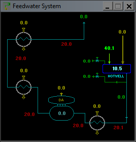
If the hotwell level rises, maybe something is pouring water into it. Indeed, Schematics > Feedwater System shows an incoming flow of water.
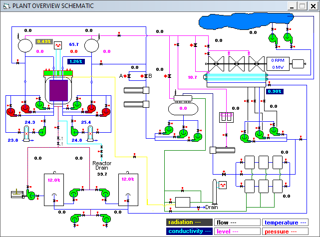
Where does it originate from? In Schematics > Overview, the condenser doesn’t seem to be connected to anything that produces water, and all the pumps are off.
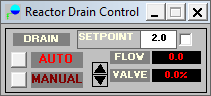
The only flow of water on the overview schematics is the reactor drain. Let’s verify that in Schematics > Steam Drum Flows.
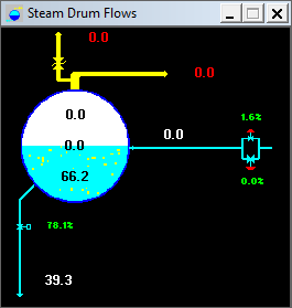
The bottom pipe corresponds to the reactor drain that evacuates water from the reactor. The flow is identical to the one entering the hotwell. The reactor drain valve is controlled from the Reactor Drain Control system that tries to maintain the drum level setpoint.
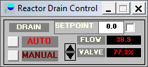
If this valve is open, that means there is too much water in the reactor, but that doesn’t tell us where this excess water comes from in the first place. The steam drum schematic shows no input flow, meaning the amount of water in the steam drum doesn’t increase. Because the drum level stays constant, despite the drain being open, we can conclude that the water is expanding. Schematics > Reactor Core Status confirms that the core temperature is slowly increasing.
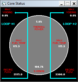
Nuclear fission doesn’t stop when you lower all the control rods. Radioactive decay produces thermal energy at a low but non-negligible level. Because no cooling system is currently enabled, the core temperature rises. And when something gets heated, it expands. Thus, the root issue is that nothing is cooling the reactor.
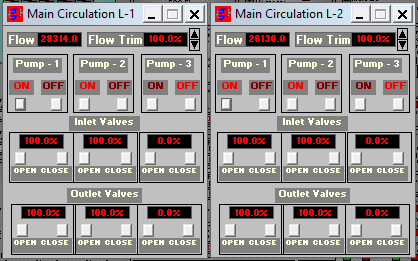
The Off-line Core Cooling System (OCCS) is responsible for this task. It comprises two powerful recirculating pumps on two loops that force water through heat exchangers. For these pumps, the same general start-up procedure outlined in “How Do I Properly Start a Large Piece of Equipment” applies:
- Open the inlet valve.
- Start the pump.
- Open the outlet valve.
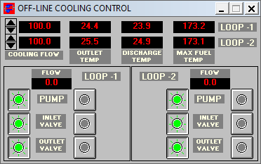
This control panel shows the “outlet” temperature, actually measured before the heat exchanger, the discharge temperature, measured after, and the maximum fuel temperature. You should try to keep them stable so the water in the core is neither expanding nor contracting, which prevents draining excess water to the hotwell. After the reactor is stopped, the accumulated fission products generate additional thermal energy for some time, but they will eventually decay, so you will have to adjust the pump flow accordingly.
For now, increase the flow to reduce the fuel temperature and keep the discharge temperature below 140°F.
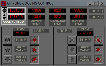
If the discharge temperature exceeds that threshold, for instance, in the first loop, you will get the alarm “off line temperature high in loop 1”, followed shortly after by “radiation leak in SDC HX-1”, meaning the shutdown cooling (SDC) heat exchanger (HX) on loop 1 has been damaged. Use Repairs / Replacements > Repair S/D Heat Exchanger Loop 1 to fix it.
Now that the OCCS is in service, you can stop the main circulation pumps (MCP) for both loop:
- Close the outlet valve.
- Stop the pump.
- Close the inlet valve.
As the core temperature decreases, water compresses, which lowers the drum level, putting you at risk of having part of the fuel exposed. Additionally, we’ve been focusing on cooling the core to maintain the drum level, but that doesn’t fix the overflowing hotwell. Solving these problems is a great way to understand the flow of water from the hotwell back to the core, which is the subject of the following subsection.
4.2 Condensate system
The next step is to restore the hotwell level. From the overview schematics, there doesn’t seem to be any way to discard excess water. The Feedwater System schematics shows two outputs. They are unlabeled, but one of them corresponds to the drain.
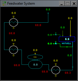
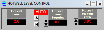
The hidden drain valve tries to keep the hotwell level under +2, but you need a condensate pump in service to move water through it. Before starting a pump, you should always make sure that you can maintain the inlet level, or you risk damaging it. Adding water back to the hotwell is the purpose of the hotwell makeup system. When the valve is set to automatic, it tries to maintain the hotwell level above the setpoint.
Because the water is supplied by the demineralized water tanks, you also have to open their flow valves.
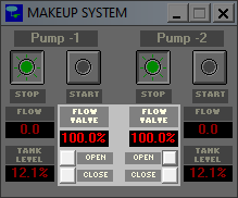
Now, you can safely put a condensate pump in service.
Because the hotwell level is above +2, the valve drains water until the level is at, or below, +2.
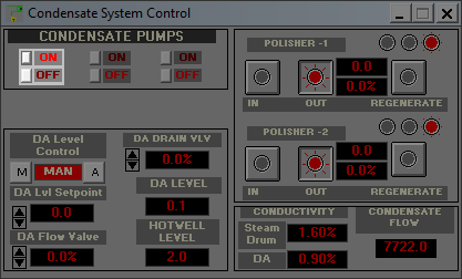
The next system in the path from the hotwell to the core is the deaerator (DA). The DA flow valve in the condensate system controls water sent from the hotwell to the DA. Currently, it is in manual mode and fully closed. Because the hotwell makeup system is in service, you can safely switch it to automatic control.
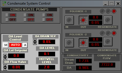
For good measure, you can put a polishing unit in service. For some reason, it reduces conductivity in the steam drum even without any flow.
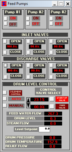
4.3 Feedwater system
The next step is to start a feedwater pump to get water from the DA to the steam drums. This is safe because the DA flow valve maintains the DA level setpoint, so unless there is a malfunction, you can’t ruin the feedwater pumps on low inlet level. In the feedwater system, the start-up valve is already selected and automatically operated to maintain the drum level at 0.
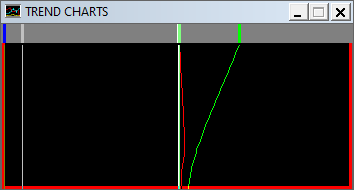
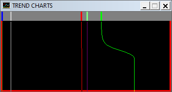
The trend charts show the coordinated action of the systems involved, with the feedwater flow in blue, the steam drum level in red, and the hotwell level in green.
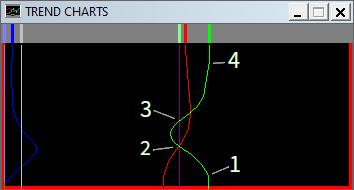
Here are the annotated data points:
- The feed pump is started and the feedwater valve is open. The water flows from the DA, whose level is maintained by the condensate system that takes water from the hotwell.
- The drum level overshoots the setpoint, so the feedwater valve closes, and the reactor drain opens. Because the hotwell level is below the setpoint, the hotwell makeup valve also opens.
- With the combined effect of the reactor drain and the hotwell makeup system, the hotwell level quickly goes back to 0, so the hotwell makeup valve closes.
- Because the reactor drain is still pouring water into the hotwell, the hotwell drain valve opens to keep the hotwell level under +2.
After some time, the feedwater flow stabilizes with the reactor drain fully open.

The reason is that the drain level setpoint is the same as the drum level setpoint: the two systems fight each other around this value. The solution is to increase the drain level setpoint to +1 or +2, so there is enough room for the feedwater valve to close before the drain valve needs to open.
As the core cools down, the volume of water in the loop decreases. Because the condensate pump maintains the DA level and the feedwater pump maintains the drum level, water ultimately comes from the hotwell. Its level decreases, so the makeup system has to inject costly demineralized water. Maintaining a steady core temperature prevents unnecessarily filling up the hotwell. In this situation, the reactor drain, the feedwater, and the DA valves should close. You can then put the condensate and the feedwater pumps out of service to reduce the electrical bill, and control the drum level only with the off-line core cooling system.
An alternative way to restore the steam drum level is to use the Emergency Core Cooling System (ECCS) instead of the feedwater system. Like the hotwell makeup valve, the ECCS takes water from the demineralized water tanks and injects it directly into the core. You could try to do that as a follow-up exercise.
5 Malfunctions
Now that you can refuel the reactor and manage the plant while it is off-line,
it is time to perform a start-up. The best way to do that is to select the last
level (IC_0004.ICD), turn malfunctions off, and follow the instructions in
“Step by Step Plant Start Up Procedure”. You should gain a better understanding
of the steam circuit.
The rest of the game consists in performing part of this start-up procedure with malfunctions on and trying to survive. The higher the difficulty, the lower the initial power level. Most of the malfunctions won’t cause any alarm unless a serious deviation from nominal parameters is detected, so you should always keep an eye on the trend charts and the schematics to identify issues before they can cause any harm.
There are three kinds of malfunctions. Some of them trigger a video from the supervisor that describes the issue. At the end, the Field Operator’s Report opens to ask a contractor to fix the issue automatically for $2000, but it is cheaper to repair it yourself.

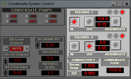
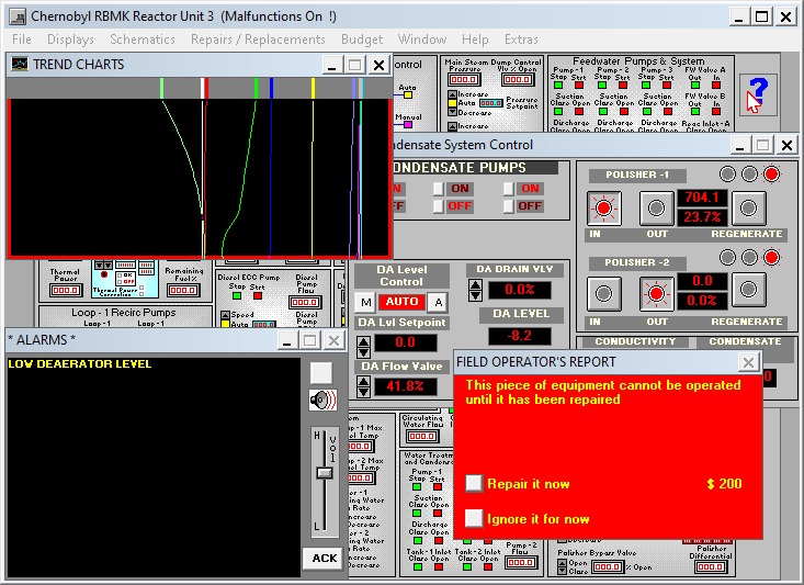
For other malfunctions, you won’t have any video that hints at the problem, so you are forced to repair them yourself. In the following example, the DA level started dropping, while the hotwell level started to increase, which indicates not enough water is sent from the hotwell to the DA. A few seconds later, the low DA level alarm appeared. If you don’t fix the problem quickly enough, you can ruin the expensive feedwater pumps.
In the Condensate System Control panel, two condensate pumps are on, DA level control is automatic, but the DA flow valve is closing instead of opening. That indicates an issue with the automatic control. You can either switch the DA level control to manual and force open the flow valve, or click on “A” to confirm automatic control, which opens the Field Operator’s Report to repair this equipment for $200 (1/10th of the contractor’s rate).
Finally, if you don’t know how to fix something from a control panel—for example, replacing the HEPA filter when it is exhausted, or repairing condenser tube leaks when the conductivity is too high—you should look into the Repairs / Replacements menu.
6 Next steps
Once you’re done with the included scenarios, there are other things you could try:
- Regular plant shutdown from full power.
- Reactor SCRAM.
- Trying to reach the maximum sustained power output.
- Operating at low power with high Xenon poisoning.
You may be wondering why I didn’t mention the Chernobyl disaster. As surprising as it may seem, Chernobyl Simulator doesn’t provide a scenario to reproduce the exact conditions of the test on that dreadful night. It is more of an RBMK nuclear power plant simulator than a Chernobyl accident simulator, but this is something I will try to remedy in an upcoming article.
As an alternative introduction, comrade Argilaga made a series of videos about this game, including a commented start-up procedure. They are based on a previous port that has some limitations, but most of his explanations should apply. The playlist also contains videos on other nuclear reactor simulation games.
To dive further on the nuclear engineering side, there are some free and open resources like the course “Introduction to Nuclear Engineering and Ionizing Radiation” from the MIT Department of Nuclear Science and Engineering.